GM has finally defeated me in my quest to change my own oil. Should be easy - a13mm socket, a wrench filter, a drain pan. Maybe a socket extension.
The vehicle in question - a 2007 GMC Acadia. Between me and the drain plug, a support for the exhaust pipe that could have been moved UP 5mm; and a chassis cross member that wouldn't have been too bad except for the exhaust support. I know they use CAD, they should check for this kind of stuff.
Better sell it before it needs new spark plugs!
This weekend is Detroit Maker Fair at Henry Ford - going to help the Frog Force, Novi FLL teams, and show off some of my stuff as well. Should be fun!
Brian
The Black Dog
Tuesday, July 27, 2010
Saturday, June 26, 2010
Getting ready for Maker Fair Detroit, Part 1
Nothing like a deadline for motivation to complete a project, and I NOW have a deadline - the Detroit Maker Fair on July 31-August 1 at Henry Ford Museum. My main goal is to get some more booth space for the Frog Force exhibit, but I'd like to get some of my own stuff out of the notebook and into hardware and software.
First up is the Coasterbot, which has a couple of improvements since the last post.

Brian
The Black Dog
First up is the Coasterbot, which has a couple of improvements since the last post.

The chassis is completely new to allow for thru bolts to hold the top and bottom coasters together. Lego plates are not the most robust connectors. The hacked mouse encoders are working nicely with the PID code on the motor control Arduino. The Coasterbot can now talk to the outside world without wires using the XBee module mounted over the left wheel (right side of robot in the picture). And buried under the wires on the main controller breadboard is an HMC6352 I2C Compass. Between the mouse encoders and the compass, I have the basis for a rudimentary navigation system. For Maker Fair, the idea is to write a Processing or .NET app to display the robot's position as reported over the XBee link on a PC (or Mac or Linux box if I use Processing) as the robot drives around avoiding objects. And there's still some room on the chassis that is just asking to be filled with some interesting bit of hardware.
Next up is an Arduino based LED clock - 60 x 3 color LEDs arranged in a circle, red indicates hours, green is minutes, blue is seconds. I've got the electronics and code prototyped, now it's more of a woodworking project. More info later as that project gets under way.
Last up (and I probably won't get to the in the next 5 weeks before Maker Fair) is an Arduino controller wireless lawn sprinkler system control to replace the hopelessly bad (at least from a user interface point of view) Toro controllers we have now. This will be a plumbing project too, since on of the main water lines out to a valve box cracked and turning on the water now results in a muddy fountain in the back yard.
Brian
The Black Dog
Thursday, May 20, 2010
It does actually work!
It actually works! The mouse encoders read correctly, they can keep up with the wheel rotation (only about 50rpm max), and everything fits on the motor plate of the MkII chassis.

Black Dog Robotics dyno test cell
Right now I'm running a modified version of the PS2 example from the Arduino website, with enough of the motor control code from the original Coasterbot program to get the wheels turning. So far, so good. Next step is to put it all together - the original Coasterbot motor control software with I2C, PS2 mouse encoder reader, and the Arduino PID Library.
The amount of knowledge out there and everyone's willingness to share it just amazes me. You really have to love the Arduino community!
Brian
The Black Dog
Tuesday, May 18, 2010
Coasterbot update
I found the top 4 entries in the MAKE Robot Build contest
#1 Jartron
#2 UFO
#3 HUL-10
#4 Tortellini
Nice work everyone!
Brian
The Black Dog
#1 Jartron
#2 UFO
#3 HUL-10
#4 Tortellini
Nice work everyone!
Brian
The Black Dog
Friday, May 14, 2010
It might actually work
A hacked up old mechanical mouse, two Lego pieces, a bit of hot glue, a piece of double sided tape and there you have it - a functional Coasterbot wheel encoder.

Or at least it looks like it might be functional - the Lego pieces will make it easy to build into the Coasterbot drivertrain, and the Arduino gets counts from the encoder. There are still a few things to test, including but not limited to:
If all the above works, then I can start work on the motor control Arduino code to implement PID, using one of the Arduino PID libraries (or writing it myself to learn what's involved).
Side note - the MAKE Coasterbot Build winners are announced today! It will be interesting to see who wins. The BDR Coasterbot should be a contender - it's strong on function, expandability, and documentation; but weak in creative use of the coasters, overall aesthetics, and maybe the design is too simplistic. It's more of a engineering exercise than an art project - I just wanted something that met the goals of the contest, and go me moving on building an expandable Arduino controlled robot. Anyway, we'll see what the results are soon.
Brian
The Black Dog

Finished encoder (left), parts required (center)
Or at least it looks like it might be functional - the Lego pieces will make it easy to build into the Coasterbot drivertrain, and the Arduino gets counts from the encoder. There are still a few things to test, including but not limited to:
- Are the encoder counts valid? The sensor and the encoder wheel have to be lined up pretty accurately in the plane of the encoder wheel (although there can be some play along the shaft axis). Also, the encoder wheel shaft and the Lego axle have to line up accurately, otherwise there will be too much runout in the encoder wheel to ever get the sensor in the right position. If this isn't right, I'll get counts for part of the revolution of the encoder wheel but not all of it - worthless.
- How many counts are there per revolution? Looks like around 130, but I have to actually count the slots to get this number precisely.
- Can the encoder keep up? I have no idea how fast the chip in the mouse runs, so I might end up with an encoder that works great, but only for low rotation rates. It would be possible to gear down the shaft driving the encoder to slow the rotation to a readable rate, or use an encoder with fewer slots, but then positioning accuracy suffers. 130 counts/rotation is 2.7 degrees per count. Gearing the read shaft down increases the degrees/count on the rotation I want to measure. Maybe OK for speed control, but not great for measuring distance to determine a position. And putting another Lego gear in the system adds more lash, reducing the accuracy even more. It might end up being a lot of work to get an answer that is less accurate than making an estimate from a pwm value/battery level/motor speed lookup table.
- Is this robust enough to handle being in the Coasterbot? The sensor isn't worth much if it works great for 2 minutes then falls apart. If it looks promising but not strong enough, I'll have to figure out a better way to mount the encoder wheel and sensor. Maybe drilling a hole in the encoder wheel and mounting it on the axle, then building a housing for the sensor and LED so the final product would look something like an RCX rotation sensor.
If all the above works, then I can start work on the motor control Arduino code to implement PID, using one of the Arduino PID libraries (or writing it myself to learn what's involved).
Side note - the MAKE Coasterbot Build winners are announced today! It will be interesting to see who wins. The BDR Coasterbot should be a contender - it's strong on function, expandability, and documentation; but weak in creative use of the coasters, overall aesthetics, and maybe the design is too simplistic. It's more of a engineering exercise than an art project - I just wanted something that met the goals of the contest, and go me moving on building an expandable Arduino controlled robot. Anyway, we'll see what the results are soon.
Brian
The Black Dog
Friday, May 7, 2010
3 More Days?!
MAKE changed the entry deadline for the Coasterbot build - it was May 7 (today, Friday), now it's May 10th (Monday). Damn them, not only 3 more days, but it's over a weekend...
The competition has set the bar pretty high - Curl, HUL 10 Version 2, Crepton, and Mult-CD all look pretty sweet. So I may need to up my game a bit by adding motor encoders. Fortunately, the Arduino community comes to the rescue again with a nice write up of interfacing to a PS2 mouse. Using this code I was able to get rotation and switch info back from the mouse this morning. Off loading the quadrature encoding to the mouse chip is a good idea - lightens the load on the motor control Arduino considerably. And I get 3 free switches. All for the cost of 2 digital pins on the Arduino.

I don't think the mouse will fit in the Coasterbot as is LOL (and the encoders aren't oriented the way I need them anyway), so I'm going to have to do some cutting to make it fit.


The competition has set the bar pretty high - Curl, HUL 10 Version 2, Crepton, and Mult-CD all look pretty sweet. So I may need to up my game a bit by adding motor encoders. Fortunately, the Arduino community comes to the rescue again with a nice write up of interfacing to a PS2 mouse. Using this code I was able to get rotation and switch info back from the mouse this morning. Off loading the quadrature encoding to the mouse chip is a good idea - lightens the load on the motor control Arduino considerably. And I get 3 free switches. All for the cost of 2 digital pins on the Arduino.

a good use for a dead mouse
I don't think the mouse will fit in the Coasterbot as is LOL (and the encoders aren't oriented the way I need them anyway), so I'm going to have to do some cutting to make it fit.


cut on the black lines...

a little hot glue and I'll have a Lego compatible encoder wheel
The hardware won't be too bad, but there's a lot of code to change in the motor controller to make use of the encoder info. We'll see if I have time this weekend - Ironman 2 came out yesterday, I'm judging all day Saturday at Robofest, Sunday is Mother's Day. So I might not get it done this weekend, but I'll give it a try.
Brian
The Black Dog
Monday, May 3, 2010
Whew!
It's done - the entry for the Coasterbot challenge, that is. Shot, edited, and posted the better quality video on youtube, filled out the entry form at MAKE, did the final edit on the Google slideshow, posted all the pictures to Flickr and uploaded the code to Scribd.
On of the questions in the MAKE entry form was "What did you learn during this project?" I didn't think of it at the time, but probably the most important thing I learned was how to use all the web-based tools available to pull together and document the project.
There will be more entries on the Coasterbot later - I plan on using it as a base platform for experimenting with more sensors and navigation software, and I'll have to announce the contest results sometime in mid-May. But for now I have some other projects in mind. Stay tuned....
Brian
The Black Dog
Sunday, May 2, 2010
As usual, the documentation takes forever...
Although the blog has been pretty quiet lately, I've been busy working on the entry for the MAKE Coasterbot build. Here's the Black Dog Coasterbot slideshow.

The slideshow isn't quite complete - I changed the behavior of the robot from 'locate and avoid' to just 'avoid'. Just avoiding obstacles is simpler, and actually shows the robot's capabilities better in a small area with lots of obstacles. I need to publish the state diagram for this.
I also need to update the control schematics to reflect the addition of the front bumpers.
And finally, I need to get a video of the robot doing it's thing.
But it's pretty close to done - should have no trouble getting it completed for the contest deadline on May 7th.
Brian
The Black Dog
Tuesday, April 20, 2010
The beginnings of a state machine
The Coasterbot continues to progress nicely. I have to enjoy it while it lasts, I'm sure there's some big roadblock waiting out there somewhere.
I have the framework for a state machine roughed in, I2C works for both sending speeds to the motor controller and receiving speeds from the motor controller (that took a while - Arduino as master sending data or slave receiving data is pretty well documented; I had to make a few educated guesses and try a couple of things to get sending data from the slave in response to a master request to work correctly). Test code and preliminary state diagram are included below. The test code just tests state changes and motor speed send/receive. I'll start writing the real code to implement the behavior described by the state diagram soon.
To make it easier to tell what's going on with the robot, I added 4 LEDs to display the robot's current state in binary (up to 16 states, 0-15). I considered saving a digital port on the master Arduino by just using 3 LEDs (8 states, 0-7), but since the intention is to expand the functionality of this robot at some point, I added the 4th LED. You can't really see it very well in the picture, but each LED is connected from the Arduino to ground through a 330 ohm resistor soldered to the cathode leg.

looks like 10 1/2 to me... .
I do need to come up with better power connections for the IR sensors, they keep falling off. And the start switch appears to be a little sticky. Minor issues. Still looking out for that roadblock....
Brian
The Black Dog
Preliminary state diagram

Coaster Master I2C 04-20-10
Coaster Motor I2C 04-20-10
Monday, April 19, 2010
I2C is easy (with a little help)
One thing I really like about working with the Arduino is the huge amount of sample code available. I was a bit concerned about getting I2C to work for this project, but with resources like the Wire library reference, Absences, Keith's Electronics Blog, and Near Future Labs, it took about 30 minutes to integrate basic I2C communications into the motor test code I already had. The master Arduino is now sending motor control commands for the slave Arduino to execute. And more importantly, the slave is executing them!
And I was so looking forward to debugging some I2C messages with the Logic analyzer - not!
Brian
The Black Dog
Coaster Master I2C
Coaster Motor I2C
And I was so looking forward to debugging some I2C messages with the Logic analyzer - not!
Brian
The Black Dog
Coaster Master I2C
Coaster Motor I2C
Saturday, April 17, 2010
Sensors connected, let the testing begin!
Got the sensors attached, connected, and tested while watching some of the FIRST Championship matches from Atlanta this morning.

front facing Sharp GP2Y0D810Z0F digital IR and Maxbotix EZ-1 sonar distance sensors
This robot will find and drive toward obstacles, stopping short of hitting them. The Maxbotix sonar will find distant obstacles and keep the robot on path towards the selected one. The Sharp IR sensors will trigger around 10cm to stop the robot short of contact. After it finds the obstacle, it will spin around and target another. At least that's the theory...
I also found how to embed scrollable text in the blog (use Scribd) which will be handy for the next phase of the project - writing the code for the master and slave Arduinos.
Here's the Arduino code for testing the sensors:
CoasterBot Sensors TestSample output:
Test Output
Brian
The Black Dog
Friday, April 16, 2010
It Moves!
I finished most of the major hardware construction for the Coasterbot over the last few days, and got to test drive it this morning. Here's a recap of what's been completed.
Control schematics:
Top layer has master Arduino and voltage regulation, bottom layer has slave Arduino and motor control. No bumper sensors included yet.


The Quad H Bridge I'm using is the SN754410. It's good for 1 amp which is fine for the Lego 43362 motors I'm using. For more details on Lego motor performance, check out the testing done by Philippe Hurbain (Philo). His book 'Extreme NXT' written with Michael Gasperi shown on his home page is excellent, although maybe a bit dangerous to your NXTs...
The drivetrain is completed on the bottom layer. The top of bottom layer has the motors and motor controls, the bottom has battery pack. Ground clearance is a little low, but this robot isn't intended for rough terrain so it should be OK. I deliberately showed up the Eneloop label on the rechargeable batteries - these work really well and have save me a lot of money compared to alkaline disposables. And kept a lot of batteries out of the landfill.
Test code for the drivetrain just runs the motors from 0% to 100% forward, 0% to 100% reverse, spins clockwise, spins counterclockwise, then repeats.

drivetrain (left), master controller (right) ready to be joined up.

battery pack with 6 Eneloop AA rechargeable batteries
low clearance, this is a smooth surface only robot
Top layer master control
The master control on the top layer is wired on the breadboard and mounted, but it really doesn't do much yet. All the code does is wait for the start switch to be pressed, then flashes the built in LED on the Arduino. The voltage regulator is assembled and tested, so I have 5V for logic and 9V for the motors.
I put the master breadboard on the back half of the top coaster for weight distribution so the robot doesn't fall on it's nose when stopping. It also gives me access to the spindle hole for running wiring between the two layers.

ready to test

every robot builder should have a grid pattern on their kitchen floor
To Do list
Even though the robot rolls, there's still plenty to do:
- Mount and connect bumpers - either mechanical or digital distance sensors
- Solder headers on Arduinos for I2C - the analog ports A4 and A5 used for I2C on the Arduino Pro Mini aren't on the edges, so I didn't put headers on them when I put the other headers on.
- Test motor balance at various speeds and develop a lookup table for the motor controller. The idea here is internally adjust a given input speed so that both motors turn at the same rate and the robot drives more or less straight. More on this later when I start to do the mapping.
- Define the I2C messages the master and slave will use for communications. There will probably be a blog entry or two on this subject. And another chance to use my Saleae Logic analyzer!
- Get I2C working between the master and slave.
- Master control software for basic obstacle avoidance.
- XBee communications back to PC for status messages. This is optional, I might just run out of time to do it before the end of the MAKE Coasterbot contest.
- More stuff I'm sure I haven't considered yet.
But first, it's a beautiful day here in SE Michigan - time to go for a mountain bike ride!
The Black Dog
Saturday, April 10, 2010
There's an NXT in there somewhere....
The Black Dog Robofest team competed last night. Tied for third in a field of 14 Senior teams, but only the top two teams advanced to the Michigan state championships so the season came to an earlier end than we'd hoped. It's too bad Robofest eliminated the Technical award that could advance you as well, I think we would have won any technical award hands down.


quick, locate the NXT on this robot
"Benson the Otter-bot" summary:
- Lego NXT control
- 1 Lego NXT light sensor
- 3 Lego NXT motors with rotation counters
- Black Dog designed I2C sensor interface controlling
- 3 Sharp short range IR distance sensors, converted to digital signals through a BDR designed and built comparator circuit
- 1 Maxbotix Ultrasonic distance sensor
- RCX motor through an H bridge built into the I2C expansion board
More details later (Eagle files for I2C board, RobotC code, etc).
Brian
The Black Dog
Brian
The Black Dog
Thursday, April 8, 2010
Yet Another Project
Kind of ironic, I've been too busy working on robots to keep up with my robotics blog. Things should slow down a little soon - the Black Dog Robofest team competes in their Michigan regional qualifier tomorrow in Ann Arbor, and the Novi High School Frog Force 503 team leaves for the FIRST World Championships in
Atlanta next week. I plan on posting more about what I've learned from mentoring those two teams this year after their seasons are over.

Even though I've been busy, I couldn't resist taking on another project - the Make Robot Build contest. The challenge is to build a robot that can navigate through a space avoiding obstacles using 2 coaster-ized CDs as the main chassis components. You can read all about the challenge here. The small footprint is a challenge - after looking at the start of my chassis, one of the kids on the Robofest team suggested trying 2 LPs instead. I was surprised they even know what an 'LP' is!
My plan is to stick with a pretty conventional mechanical design - 2 wheel differential drive, PWM speed control, a trailing caster, contact switches for bumpers. For expandability (one of the judging criteria) I'll be using 2 Arduino Pro Minis - one dedicated to motor control, the other for sensor input and overall robot control. At this point, I could do all control using a single Arduino, but once I add sensors and more sophisticated motor control, I want to be able to split up the work. The Arduinos will communicate using I2C or serial - I2C makes it easy to add more nodes on the bus, and I want to learn how to use the Arduino 'Wires' I2C library, but I may go with serial for now if I get short on time.
To keep the cost down to zero, I'm using components already on hand:
I guess it's easy to keep the cost down when you have a lot of stuff lying around already.
The bottom coaster carries the drivetrain - motor battery pack on the bottom, breadboard for the slave Arduino and motor driver, and the drive motors on top. The ball caster attaches to the back of the bottom coaster. There's room on the bottom coaster to add some kind of wheel rotation counters for PID control and
distance measurement in the future.


The top coaster will carry the master controller and sensors - the second breadboard on top for the master Arduino and possibly a 5V regulator for logic power; bumper switches and possibly batteries for logic power on the bottom. There's even a nice pre-drilled hole in the middle of the top coaster for passing wires through to the drivetrain controller!
The top coaster will have room for more sensors - IR and/or sonar distance, accelerometer, gyro, compass, vision (OK, I probably have too much stuff 'lying around'). My main interest is in navigation - integrating all the various sensors into a position estimate and mapping the environment around the robot. Eventually that leads to learning how to use the Kalman filter (I haven't seen notation like that since college, and I certainly don't remember it!).
The basic build is relatively straightforward. Coding is another issue....
Brian
The Black Dog
Atlanta next week. I plan on posting more about what I've learned from mentoring those two teams this year after their seasons are over.

the new project
Even though I've been busy, I couldn't resist taking on another project - the Make Robot Build contest. The challenge is to build a robot that can navigate through a space avoiding obstacles using 2 coaster-ized CDs as the main chassis components. You can read all about the challenge here. The small footprint is a challenge - after looking at the start of my chassis, one of the kids on the Robofest team suggested trying 2 LPs instead. I was surprised they even know what an 'LP' is!
My plan is to stick with a pretty conventional mechanical design - 2 wheel differential drive, PWM speed control, a trailing caster, contact switches for bumpers. For expandability (one of the judging criteria) I'll be using 2 Arduino Pro Minis - one dedicated to motor control, the other for sensor input and overall robot control. At this point, I could do all control using a single Arduino, but once I add sensors and more sophisticated motor control, I want to be able to split up the work. The Arduinos will communicate using I2C or serial - I2C makes it easy to add more nodes on the bus, and I want to learn how to use the Arduino 'Wires' I2C library, but I may go with serial for now if I get short on time.
To keep the cost down to zero, I'm using components already on hand:
- 2 coaster-ized CDs
- 2 Lego RCX motors
- 2 Arduino Pro Minis
- 1 L298N Dual Motor Driver and Sparkfun breakout board
- 2 breadboards
- 1 Tamiya Ball Caster
- Various Lego gears, wheels, plates, and beams
- Scavenged switches for bumpers
- XBee module for transmitting navigational info to a remote computer for analysis (one way communication only, the robot will be autonomous)
I guess it's easy to keep the cost down when you have a lot of stuff lying around already.
The bottom coaster carries the drivetrain - motor battery pack on the bottom, breadboard for the slave Arduino and motor driver, and the drive motors on top. The ball caster attaches to the back of the bottom coaster. There's room on the bottom coaster to add some kind of wheel rotation counters for PID control and
distance measurement in the future.

back view of drivetrain. cross brace between tops of motors for support until top coaster goes on.

bottom view of the drivetrain coaster. got to get some shorter bolts....
The top coaster will carry the master controller and sensors - the second breadboard on top for the master Arduino and possibly a 5V regulator for logic power; bumper switches and possibly batteries for logic power on the bottom. There's even a nice pre-drilled hole in the middle of the top coaster for passing wires through to the drivetrain controller!
The top coaster will have room for more sensors - IR and/or sonar distance, accelerometer, gyro, compass, vision (OK, I probably have too much stuff 'lying around'). My main interest is in navigation - integrating all the various sensors into a position estimate and mapping the environment around the robot. Eventually that leads to learning how to use the Kalman filter (I haven't seen notation like that since college, and I certainly don't remember it!).
The basic build is relatively straightforward. Coding is another issue....
Brian
The Black Dog
Friday, March 12, 2010
Talk to 'The Judge'
This should have been a really simple project, maybe an hour max. It really should not have taken all last Sunday afternoon, if I had just remembered one key fact....

I've been involved in putting on the annual Pinewood Derby for the Novi Girl Scouts for the last 7 years or so, and I did a few years of Cub Scout Derbys before that. I'm the Bernie Ecclestone of Novi Pinewood. Our current setup is a 4 lane BestTrack, with The Judge race timing hardware (above) and Grand Prix Manager software. This combintation that works great, except for one small issue....
Back when I started doing Pinewood Derbys, every computer had at least one serial port available for connecting the race timing hardware to the computer. But now it's 10 years later. The timing hardware still uses serial communications, but serial ports are pretty rare especially on laptops. Trying to scrounge up a computer with a serial port, or a USB-Serial converter in the week or so before the race was getting to be a pain. I wanted to put together something that would stay with the track, and I had an idea.
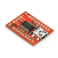
I've used various FTDI breakout boards from Sparkfun for Arduino projects. They're cheap, small. and, more importantly, I had an extra FT232RL in my parts box. At $15, they're $20-$30 cheaper than a USB-Serial from Best Buy or Radio Shack. It's also small enough to build right onto The Judge's Junction Box (see photo below). I could build it right into the track, put the driver software on a USB stick to stay with the track. Problem solved. And since the DB9 connector on the Junction Box got ripped out last year when someone stepped on the serial cable, I didn't even have to remove anything - just solder TX, RX, and ground connections between the Junction Box and the FT232RL Breakout Board, plug it in and start getting race results.

The garbled characters look like a baud rate issue. Try Hyperterminal with various baudrates from 1200 up. Same results. Back to 9600 baud. And now I start to go into the wilderness for a couple hours.
The Judge runs on 3 AA batteries; 4.5 volts on a good day. The batteries check out OK, could it be that the logic level on The Judge isn't close enough to what the FTDI breakout board is expecting? The breakout board has a VCCIO pin to allow you to provide a different reference voltage, and the Junction Box exposes it's VCC for the magnetic switch supply - connecting those should.... dang not do it either!
Did I really get the wires connected correctly between the Junction Box and the FTDI breakout? Yep, looks good. In retrospect, this check should have been done sooner in the process, but since it was OK it didn't hurt me.
Maybe The Judge is messed up - it's been in the basement all year after all. Find a computer with a serial port, desolder the FTDI board, find a serial cable, hook up The Judge to the new computer... this is starting to take longer than I expected.... The serial port setup works, so the Judge is good, and it is communicating at 9600/8/1/None. Not a complete loss, since 2 variables (does the Judge work, and is the baud rate correct) have been eliminated.
Reconnect the FTDI breakout into the Junction Box wiring, this time on a breadboard so I can change wiring easier. Same results, a garbled mess.
At this point I get a little smarter and decide to use my Saleae Logic analyzer. Connect the Logic to the serial line, select the Asynchronous Serial analyzer in ASCII mode so I can see the characters. Start up The Judge and.... Logic sees junk too! Is it the FTDI messing things up? Disconnect the FTDI breakout, reconnect The Judge to the serial port on the computer. Start Hyperterminal and The Judge and.... Hyperterminal sees the diagnostic message, but Logic still sees junk! How is this possible?!
At this point I'm beginning to get a little nervous. It's Sunday afternoon, I've burned 3 or so hours on a one hour project and I'm stuck. The Pinewood Derby is Thursday evening. I've got a somewhat minor surgery scheduled for Tuesday and I'm not sure how much I'll be able to do on Tuesday and Wednesday. Time to rethink the process.
Change the logic analyzer to show hex instead of ASCII. Hmmm... now we're getting somewhere. The hex values of the junk characters are all 0x80 or higher (128 decimal). Regular ASCII characters should below 0x80 (128). If we invert that 0xB5, we get 0x4A. That's a 'J'! Inverting the next few bytes gives me 'u', 'd', 'g', and 'e'. I don't think this is a coincidence!
Being a software guy, I'm not sure I ever knew you could invert the sense of a serial line - low votage means 1, high voltage means 0. If I did, I had certainly forgotten it by last Sunday! But a little research on the FTDI site showed me how to make the FT232RL understand inverted logic levels coming from The Judge. Reset the FT232RL, reconnect everything, it works!
Moral of the story - go to the Logic Analyzer sooner. Oh, and don't leave checking out the hardware to the last possible minute.
Next year, maybe I'll convert everything to wireless with a couple of XBee modules....
Brian
The Black Dog
P.S. - the derby went off without a single hardware problem!
I've been involved in putting on the annual Pinewood Derby for the Novi Girl Scouts for the last 7 years or so, and I did a few years of Cub Scout Derbys before that. I'm the Bernie Ecclestone of Novi Pinewood. Our current setup is a 4 lane BestTrack, with The Judge race timing hardware (above) and Grand Prix Manager software. This combintation that works great, except for one small issue....
Back when I started doing Pinewood Derbys, every computer had at least one serial port available for connecting the race timing hardware to the computer. But now it's 10 years later. The timing hardware still uses serial communications, but serial ports are pretty rare especially on laptops. Trying to scrounge up a computer with a serial port, or a USB-Serial converter in the week or so before the race was getting to be a pain. I wanted to put together something that would stay with the track, and I had an idea.
I've used various FTDI breakout boards from Sparkfun for Arduino projects. They're cheap, small. and, more importantly, I had an extra FT232RL in my parts box. At $15, they're $20-$30 cheaper than a USB-Serial from Best Buy or Radio Shack. It's also small enough to build right onto The Judge's Junction Box (see photo below). I could build it right into the track, put the driver software on a USB stick to stay with the track. Problem solved. And since the DB9 connector on the Junction Box got ripped out last year when someone stepped on the serial cable, I didn't even have to remove anything - just solder TX, RX, and ground connections between the Junction Box and the FT232RL Breakout Board, plug it in and start getting race results.
After the serial connections were made, I connected the USB cable, started up Windows Hyperterminal, selected the USB to Serial COM port, set the port to 9600/8/1/None per the New Directions website, put the batteries in 'The Judge', and went online with Hyperterminal. What should have been a readable status message from The Judge was just a garbled mess. Hmmm...
The garbled characters look like a baud rate issue. Try Hyperterminal with various baudrates from 1200 up. Same results. Back to 9600 baud. And now I start to go into the wilderness for a couple hours.
The Judge runs on 3 AA batteries; 4.5 volts on a good day. The batteries check out OK, could it be that the logic level on The Judge isn't close enough to what the FTDI breakout board is expecting? The breakout board has a VCCIO pin to allow you to provide a different reference voltage, and the Junction Box exposes it's VCC for the magnetic switch supply - connecting those should.... dang not do it either!
Did I really get the wires connected correctly between the Junction Box and the FTDI breakout? Yep, looks good. In retrospect, this check should have been done sooner in the process, but since it was OK it didn't hurt me.
Maybe The Judge is messed up - it's been in the basement all year after all. Find a computer with a serial port, desolder the FTDI board, find a serial cable, hook up The Judge to the new computer... this is starting to take longer than I expected.... The serial port setup works, so the Judge is good, and it is communicating at 9600/8/1/None. Not a complete loss, since 2 variables (does the Judge work, and is the baud rate correct) have been eliminated.
Reconnect the FTDI breakout into the Junction Box wiring, this time on a breadboard so I can change wiring easier. Same results, a garbled mess.
At this point I get a little smarter and decide to use my Saleae Logic analyzer. Connect the Logic to the serial line, select the Asynchronous Serial analyzer in ASCII mode so I can see the characters. Start up The Judge and.... Logic sees junk too! Is it the FTDI messing things up? Disconnect the FTDI breakout, reconnect The Judge to the serial port on the computer. Start Hyperterminal and The Judge and.... Hyperterminal sees the diagnostic message, but Logic still sees junk! How is this possible?!
At this point I'm beginning to get a little nervous. It's Sunday afternoon, I've burned 3 or so hours on a one hour project and I'm stuck. The Pinewood Derby is Thursday evening. I've got a somewhat minor surgery scheduled for Tuesday and I'm not sure how much I'll be able to do on Tuesday and Wednesday. Time to rethink the process.
Change the logic analyzer to show hex instead of ASCII. Hmmm... now we're getting somewhere. The hex values of the junk characters are all 0x80 or higher (128 decimal). Regular ASCII characters should below 0x80 (128). If we invert that 0xB5, we get 0x4A. That's a 'J'! Inverting the next few bytes gives me 'u', 'd', 'g', and 'e'. I don't think this is a coincidence!
Being a software guy, I'm not sure I ever knew you could invert the sense of a serial line - low votage means 1, high voltage means 0. If I did, I had certainly forgotten it by last Sunday! But a little research on the FTDI site showed me how to make the FT232RL understand inverted logic levels coming from The Judge. Reset the FT232RL, reconnect everything, it works!
Moral of the story - go to the Logic Analyzer sooner. Oh, and don't leave checking out the hardware to the last possible minute.
Next year, maybe I'll convert everything to wireless with a couple of XBee modules....
Brian
The Black Dog
P.S. - the derby went off without a single hardware problem!
Wednesday, March 10, 2010
Yet another robotics blog
Although I'm a software developer by profession (over 30 years now?!), I've been working with hobby robotics/electronics since getting a Lego RCX set for "the kids" around 1999. The purpose of this blog is to document the projects I've been working on or pretty much anything I find interesting.
My interest in electronics really took off when I started mentoring teams for Lawrence Tech Robofest in 2005. Our teams started off with pretty much standard Lego RCX and Mindstorms NXT, but as we progressed we found we needed more sensors, and ended up developing some using the I2C interface available on the NXT. This year I started working with Frog Force 503 - Novi High for FIRST Robotics, helping the kids develop a 512 3 color LED cube and a Meccanum drive for a demonstration robot.
I've been attending GO-Tech meetings in Ann Arbor (a seriously eclectic group of people!) on and off for a couple of years, doing a lot of little projects with the Arduino development platform, getting plenty of little red boxes from Sparkfun, and reading MAKE magazine since the first issue.
Enough name dropping! Next post will document connecting 'The Judge' (a Pinewood Derby timer) to a USB port using a FTDI breakout board from Sparkfun (I have a feeling name-dropping will be unavoidable for this blog...)
Brian
The Black Dog
Subscribe to:
Posts (Atom)